


| |
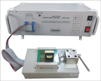
Automatic Transformer Tester
Computerized LCRTZ Test System (CVCT-S20)
Ideal for fast and fool proof testing of COILS AND SMALL TRANSFORMERS like SMPS transformers, Telecom transformers (HYBRID, POT CORE, RM-CORE), Pulse transformers etc. The systems scans at one stroke, all the windings of a transformer and tests as per definition of test procedure. The test procedure can be pre-programmed and stored under User friendly menu driven software . Any semi-skilled and unskilled person can be engaged for actual testing purpose. Can Select test frequency, pin number, parameters, test conditions, limits for each test. Test any pin to any other pin any defined parameter.
|
|
Test parameters include
-
Inductance
-
Capacitance
-
AC Resistance,
-
DC Resistance,
-
Impedance,
-
Leakage Inductance,
-
Transformation Ratio & Winding Polarity
|
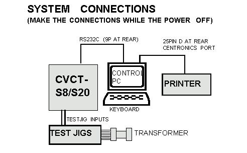
PC Control Software
The instrument is controlled through external PC through RS232C port. The system stores the test results to database tables. The system software works on Windows platform.
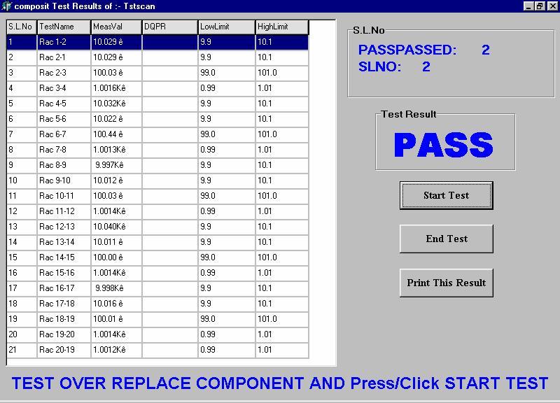
View & Print Test Results (Database)
All the test results will be transferred to a database files with connected file name. The database table is compatible to fox-pro table. You can import these files to other
software for creating graphs and other analysis.
SPECIFICATIONS :
Measurement Frequencies: 50,
100, 500, 800 HZ; 1K, 2K, 5K, 10K HZ.
Measurement Voltage: 0.1
V – 1.0 V RMS adjustable under program control.
Four terminal or Kelvin type of testing:
Provided to eliminate lead resistance.
| Test
Parameter |
Range |
Accuracy |
| INDUCTANCE (L) |
0.1 uH-100H |
+0.2%+1dgt @1KHZ, +0.5%+1dgt
@ Other Freq. |
| RESISTANCE (Rac) |
0.01 Ohm- 200Kohm |
+0.2%+1dgt @
1KHZ, +0.5%+1dgt
@ Other Freq. |
| RESISTANCE (Rdc) |
0.01 Ohm - 20Kohm |
+0.2%+1dgt |
| IMPEDANCE (Z) |
0.01 Ohm - 200Kohm |
+0.2%+1dgt @
1KHZ, +0.5%+1dgt
@ Other Freq. |
| CAPACITANCE (C) |
1pf - 200Ufd |
+0.2%+1dgt @
1KHZ, +0.5%+1dgt
@ Other Freq. |
| TRANSFORMATION RATIO (TR) |
1 - 1000T (RATIO) |
+0.2%+0.1T @
1KHZ, +0.5%+0.2T
@ Other Freq. |
| TAN DELTA (D.F.) |
0.0001-9.999 |
+0.0002+1%rdg @
1KHZ, +0.001+2%rdg
@ Other Freq. |
| QUALITY FACTOR (Q.F.) |
0.001- 999 |
+2%+0.1Q @ 1KHZ, +5%+0.5Q@
Other Freq. |
| CAP.UN BAL (CU) |
C>10nF |
+0.1%rdg +0.1%
of C |
| RES.UN BAL (RU) |
R>10 Ohm |
+0.1%rdg +0.1%
of R |
| IMP.UN.BAL (ZU) |
Z>10 Ohm |
+0.1%rdg +0.1%
of Z |
Power
Requirements: 230V+10%
50HZ AC Mains
Composite Testing window
Creating New Test Data
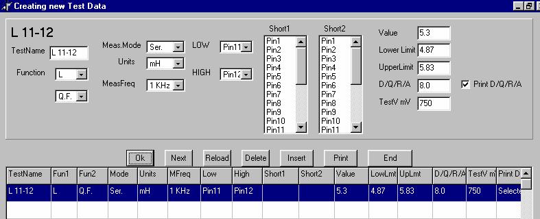
Password Requirement : The control software expects two levels of users.
Level-1 user - Person with Password: A person who understands the transformer, its windings, drawings, specifications. This person will be provided with the password and will be able to access all menu items. Level-2 user - Person without Password: This persons can select the test file, test the components and take reports.
Shorting provision : (For measurement of series aiding and for leakage inductance test )
In addition to 20 pin scanning the system has 2 rows of shorting relays to short between any two or more defined pins. Where ever you need programmed shorting, define in your test procedure. This shorting is very handy for testing parameters like Impedance and leakage inductance. With the help of these two rows you can also make two or three windings in series for measurement.
Kelvin Test : The instrument has 2 pairs of connections. One pair for drive and the other pair for sense. This separate connection can be utilized for testing transmission / transformation parameters. You will be able to test transformation ratio.
Impedance Test : Though impedance is 2 pin test, it also involves connection of load impedance or load resistance. If you are testing impedance only, you can connect the load impedance permanently to the test jig. However if you want to test multiple windings and other parameters along with impedance, you can use the shorting provided in the system.
Winding Polarity Test : In addition to Transformation ratio test, the system also checks the polarity of winding with respect to reference winding. If the secondary is not in phase with primary then the system displays -ve sign.
Unbalance Test : This test calculates the percentage unbalance of the previous two tests. You can measure unbalance of Inductance, Capacitance, Resistance and Impedance. If the individual readings are R1 and R2 then
UNBALANCE= (R1-R2) x 100
(R1+R2)
Testing Speed : Less than 0.75 seconds per each test. If there are 4 tests in a transformer it takes about 3 seconds or less after inserting the transformer into the test jig.
Data
Sheet ;  Demonstration Video
|

 :
vasavielectronics
:
vasavielectronics